Virtual Reality
COMPSCI 118
- Introduction
- Rendering
- Graphics Pipeline
- VR Display
- Stereo Display
- Sound
- Tracking
- Human Factors
- Interaction
Introduction
-
Formal definition: Using targeted behavior in an organism using artificial sensory simulation with little or no awareness of the interference on the part of the organism
- Targeted behavior: A man-made experience
- Organism: Any organism, not just human
- Targeted behavior: One or more senses are “taken over” (at least partially) by the virtual world
- No awareness: “Fooled” to feel like the real world; sense of presence
- Music, movies, and paintings can be thought of as “virtual reality” through this definition
- Defined by Immanuel Kant as the reality in someone’s mind
- Jaron Lanier also defined a real world (the physical world) and a virtual world (the perceived world)
- Different terms for VR: Augmented reality (AR), mixed reality (MR), XR, telepresence, teleoperation
- Open Loop vs. Closed Loop: Open loop systems don’t allow for the user to interact, while closed loop systems do
- Components
- Tracking: Input from user, looks at hand, head, body, etc. movements
- Software: Renders and controls the virtual world
- Maintains consistency between real world and virtual world
- Matched zone; users should be able to walk in the real world to walk in the virtual one
- Display: Outputs the virtual world to the user
- The computer links all these things together
- A VR headset uses two different images for your two eyes in order to create the illusion of depth
- Instead of obscuring all other vision, AR uses pass-through monitors as lenses in order to project virtual objects onto the real world
- SAR wants to get rid of any wearables (i.e. headsets) and allow for seamless merging between the virtual and real worlds
- Some challenges with VR headsets
- Vergence: Headsets will cannot emulate aspects of depth; eyes will try to focus on something far away, but the screen will stay the same, causing discomfort to the user
-
Law of Weber and Stephen: Users will be able to physically feel a difference depending on their stimulus
- $P=KS^n$, where $K = \frac{\text{Difference Threshold}}{\text{Standard Weight}}$ is the Weber fraction, $P$ is the perception, and $S$ is the stimulus strength
- If $n>1$, then we have expansion; if $n<1$, we have compression
- Electric shocks follow expansion (double the shock is more than double the pain), whereas brightnesss follows compression (double the light is less than double the brightness)
- McGurk Effect: If the lip sync and audio are different, you hear something different
- Early VR headsets included stereoscopes, HMD, Nintendo’s Virtual Boy
Rendering
- Has multiple inputs
- 3D world: objects, lights, materials, textures
- Camera location, orientation, FoV
- Output: 2D image of the world from the camera
- Graphics Pipeline
- Modeling: Coordinate system and objects
- Viewing: Camera/eye, gets rid of objects not being seen
- Illumination and shading
- Rasterization: Creating a 2D image from the 3D world
- Texture mapping
-
Triangle Soup Model
- Vertices have a number of attributes, such as coordinates, colors, normals
- Normals define the direction a face is oriented; can be calculated by averaging the normals of the nearby vertices
- Triangles are defined as objects that connect vertices
- Vertices have a number of attributes, such as coordinates, colors, normals
- Techniques
- Rasterization: Project vertices from 3D onto 2D space and draw triangles between them to represent the polygons; done by the GPU
-
Interpolation: Automatically generating transitions between colors, frames, polygons, etc.
- Creates interpolation coefficients by averaging out the colors/normals of nearby vertices
- Transformations
-
Scaling: Apply a scaling matrix, defined as $S(s_x, s_y, s_z)$ onto a point to transform it
- Matrix has parameters on the diagonal; can be reversed using the inverse matrix, which is equivalent to $S(1/s_x, 1/s_y, 1/s_z)$
- Rotation: Apply a rotation matrix which rotates a point about one of the three axes using sine and cosine
-
Translation: Must use a 4D matrix and convert the 3-vector into a 4-vector
- Homogenous coordinates: A 3-vector and 4-vector representing the same point in 3D; append an extra 1
- All of the previous transformations can be converted into 4D matrices in order to work with the homogenous representation
- Shearing: Translating an object about two out of the three axes by a value proportional to the third axis; affects shape of the object
-
Scaling: Apply a scaling matrix, defined as $S(s_x, s_y, s_z)$ onto a point to transform it
- Can concatenate different transformations onto each other to perform complex operations
- Most notable is rotating/scaling about a fixed point by translating to the origin, performing the transformation, and inverting the first translation
- An affine transformation is any transformation using a 4x4 matrix where the last row is 0 0 0 1
- Degree of curve can’t be changed, and parallel lines cannot become intersecting lines
- In projective transformations, parallel lines can intersect and vice versa; used when rendering using a pinhole camera
Graphics Pipeline
- Input: Soup of triangles
- Output: Image from a particular viewpoint, produced in real time
- The output is put into the frame buffer, which is updated according to the FPS and sent to the monitor
- Steps (done in the GPU)
-
Vertex Processing: Process the vertices and normals
- Performs transformations on points and per vertex lighting
- Transformations include model, view, and projection transforms
- Rasterization: Convert vertices into a set of fragments (triangles)
-
Fragment Processing: Process individual fragments
- Performs texturing and per fragment lighting
- Output Merging: Combine 3D fragments into 2D space for the display
-
Vertex Processing: Process the vertices and normals
Vertex Procesing
-
Model Transform: Begins by arranging the objects in the world using a model transform
- Involves scaling, rotation, translation, shear transformations to propagate the world space
-
View Transform: Positions and orients the camera using a view transform
- Translate the camera to the origin ($T$) and then rotate it appropriately ($R$); final transformation is $M = RT$
-
Projection Transform: Defines properties of the camera (FOV, lens) and projects the 3D space onto the camera using a projection transform
- Uses gaze direction (shear), FOV, aspect ratio, near plane (image plane), and far plane (cuts off rest of scene) to create the 2D image
- Displays all objects inside of the view frustum which is a 3D object connecting the near and far planes
- Must be normalized (to a cube) so conversion to window coordinates is easy
- Requires shear, scale, and projective transformation to convert
- Final transformation matrix: ${v_{clip} = M_{proj} \cdot M_{view} \cdot M_{model} \cdot v}$
- Must clip objects to fit on screen by transforming coordinates again
- z-coordinate is retained for occlusion
- To make it look like the camera is coming from the right perspective, a perspective projection is applied which uses translation (to move the camera), shear (to change the LookAt value), and scaling (to convert to cuboid)
- A Viewport Transform is performed
- Uses translation to move the nearplane to the center of the window and scaling to scale it to the right size
- TLDR: Takes 3D vertices and puts them on a 2D screen, ensuring that only vertices that are “on-screen” are rendered
Rasterizer
- After clipping and retriangulating, the rasterizer “fills in” the interiors of triangles
- Main issue: Edges of triangles are non-integer, but pixels on a screen are integer; must interpolate vertex attributes onto the pixels
- One strategy is to use scanline interpolation which involves sweeping across the 2D plane to determine which pixels fall inside of a triangle and interpolating the pixel accordingly
- The z-coordinate allows the rasterizer to figure out which shapes take precedence over others via the depth buffer; known as occlusion resolution
- The rasterizer also performs lighting and shading which is extremely difficult to model due to the vast amount of light sources (direct + indirect illumination)
- Lighting
- A simple model would be to remove indirect lighting and to replace with one lighting term
-
Phong illumination/lighting calculates three channels (ambient, diffuse, specular) and combinews them to light objects
- Requires a material color and a light color for each channel
- Ambient: viewer-independent, acts as a “background color”, approximates indirect illumniation
- Formula: $m\cdot l$; does not depend on viewer, normals, or light
- Diffuse: light coming off of a surface, relies on the angle of lighting and the normal of the surface, approximates some aspects of direct illumination
- Formula: $m\cdot l \cdot \max(L\cdot N, 0)$, where $L\cdot N$ is the dot product between the light and the normal angles
- Specular: Reflected light depending on where the viewer is standing, models the shininess of objects, approximates some aspects of direct illumination
- Formula: $m\cdot l \cdot \max(R\cdot V, 0)^{shininess}$, where $R\cdot V$ is the dot product of the refelector and viewer angles
- $shininess$ is an additional parameter required for the specular channel
-
Attentuation is used to model the falloff of light intensity w.r.t. distance
- Formula for attentuation coefficient: $\frac{1}{k_c + k_ld_i + k_qd_i^2}$
- Shading
- Shading is the acutal computation of the color for each pixel/fragment/vertex whereas lighting gives the model to do so
-
Flat shading: Compute color once per triangle using some model (like Phong lighting)
- Fast to compute, but looks very unrealistic
-
Gourand shading: Compute color once per vertex and interpolate these colors to the triangles
- A little slower than flat shading, but looks a little more realistic
-
Phong shading: Compute color once per fragment which requires interpolation of per-vertex normals
- Most realistic, but slowest strategy
- Vertex shading will be done before the rasterizer while fragment shading will be done afterwards
- Texture mapping is also done in the rasterizer, and the main operation is to map coordinates from the 3D surface (x, y, z) into 2D texture coordinates (u, v)
- These coordinates are interpolated for each fragment
- Since texture coordinates are not guaranteed to be integer, we use texture filtering and use bilinear interpolation
VR Display
- Various issues with having a high quality display
-
Visual acuity: VR world must be precise, like reality - should be able to see 15 pixels per inch from 20 feet away
- Varies over different eyes
- Visual field: Seeing with one eye vs. two eyes means that the FOOV should be different
- Temporal resolution: Video should be smooth in order to not be offputting
- Depth: Depth is hard to work with; many issues exist like disparity, vergence, accomodation, blur
-
Visual acuity: VR world must be precise, like reality - should be able to see 15 pixels per inch from 20 feet away
- Biology of vision
- Eye peforms low-level processing, brain does high-level
- Most of the eye’s functions are concentrated within a small part of the eye
- Eye uses cones and rods to process color/light; short, medium, and long wave cones process RGB colors
- Each eye has its own monocular visual field that it can see
- The binocular (stereo) visual field is the overlap of the two eyes; allows you to see depth
- Monocular = periphery, binocular = fovea
- Can only see color in fovea
- The total visual field is about 200 degrees; the binocular visual field is about 120 degrees
- Headsets are limited because there is a minimum distance that people are able to focus at
- Strategy: Use two lenses, increasing the FOV and weight
- Visual acuity is difficult to achieve because the photoreceptors capture 1 arcmin of visual angle
- Leads to requiring a massive amount of pixels; high compute and data requirements
- The eye will see a certain number of “cycles” in one degree, where there are two pixels per cycle (high and low)
- This is known as the resolution, more cycles per degree means better resolution
-
Minimum Angle of Resolution: $\omega = me + \omega_0$
- $\omega$: resolution in degrees per cycle
- $e$: angle per eccentricity in degrees
- $\omega_0$: smallest resolvable angle in fovea in degrees per cycle
- Visual acuity can be calculated as the reciprocal of MAR ($\omega$)
- Use MAR to accomplish foveated rendering: Split the image into multiple layers (inner/foveal, middle, outer) based on MAR and render them as more/less blurry
- Less compute since less pixels have to be rendered; great speedup
- Use MAR to accomplish foveated rendering: Split the image into multiple layers (inner/foveal, middle, outer) based on MAR and render them as more/less blurry
- Depth can be perceived in both binocular and monocular vision
- Monocular: Accomodation, retinal blue, motion parallax
- Binocular: (Con)vergence, disparity
- Pictorial cues: Shading, perspective, texture
- Vergence: Convergence of muscles to fixate on a single object
- Accomodation: Ability of lens to focus on fixated object
- Vergence-Accomodation Conflict: Eyes try to focus on the screen in front of them, but the screen “fools” them into perceiving depth, creating a difference in vergence and accomodation; causes much fatigure
- Motion parallax: Ability to see different objects while moving
-
Retinal blur: Blurring of objects when eyes focus on something different
- Blur can be calculated using $c_z = ar\left(\frac{1}{f} - \frac{1}{z}\right)$
- $r$: Distance to sensor
- $a$: Aperture, controlled by pupil (such as by squinting)
- $f$: Focal length, controlled by accomodation
- $z$: The depth, $d$, that is focused on
- Blur can be calculated using $c_z = ar\left(\frac{1}{f} - \frac{1}{z}\right)$
Stereo Display
- One way to achieve stereo vision using 2D is through glasses
- Can use anaglyph, polarization, etc.
- General strategy: have each eye see a different color/polarization/etc., forcing them to work together to see a 3D image
-
Polarization: Each eye sees different rows + columns, i.e. right eye sees even while left eye sees odd (different polarizations)
- Popular example is RealD
- Inexpensive and makes gaze direction irrelevant
- Screen must be polarization-preserving, and this strategy loses brightness + resolution
-
Shutter: Each lens opens and closes exactly when the frame changes
- Somewhat expensive, requires fast display, screen must be synced with glasses
- Active glasses
-
Chromatic Filters: Uses two projectors to project two different colored images (one for each eye)
- Somewhat expensive, can’t use in theaters
-
Anaglyph: Render stereo images in different colors so that each eye sees a different image
- Most inexpensive glasses
- Has issues with colors
- To create a full-color anaglyph image, render a left and right image then color left using red channel and right using green + blue (red-cyan anaglyph)
-
Parallax: The relative distance of a 3D point projected into the 2 stereo images
- Positive parallax means point is behind projection plane, zero parallax means point is on the plane, negative means point is in front
- Must use horizontal parallax where both eyes have the same projection plane (screen), known as off-axis projection
- Projection previously was only from one viewpoint, but now that there are two, we have to account for the horizontal parallax
HMD Display
- Basic idea: Have a lens that is a short distance away from a micro display
- Lens magnifies the virtual image to appear at a realistic distance away from the viewer
- Must account for pincushion (inwards) or barrel (outwards) distortion created by the lens by applying the opposite distortion
Varifocal Display
- Use an actuator and an eye-tracking camera to move the screen away/towards the viewer based on where they are looking in order to remove the vergence-accomodation issue
- Instead of an actuator that moves the screen, a tunable lens with varying focus can be employed to change the distance; more expensive but less technically complicated
Sound
- Sound is the vibration of air particles, and the eardrum is able to hear sound by detecting the vibrations
- Can be simulated using bone conduction
- Stereophonic sound does not reach both ears at the same time; depends on location of sound, leading to a phase difference and amplitude difference
- Head Related Impulse Response (HRIR): The amplitude of sound heard by each ear, can be modeled using the Dirac delta function (along with some noise due to dampening + scattering to be more realistic)
- Two types of sound: point sources and ambient sound
- Point source: Find the HRIR for each ear and play the appropriate sound according to the delta function
-
Ambient sound: Sample where the sound is coming from in multiple places, and play them from those places
- Think of a living room setup: 6-8 speakers playing sounds to create surround sound
- Can sample using spherical harmonics
Tracking
- Need to track the position and orientation of the head and hands by either using Inertial Measurement Units (IMUs) or Optical Tracking with cameras
- Tracking requires sensors and angular measurements of yaw, pitch, and roll
- Vestibular System: Provides a sense of balance and gravity, senses acceleration
- Head orientation has 6 degrees of freedom
- TODO: Add vertex in clip space
IMU Tracking
- IMUs measure angular velocity ($'\omega$ in deg/s) with gyroscope, linear acceleration ($'\alpha$ in m/s2) with accelerometer, and magnetic field strength ($m$ in uT = microtesla) with magnetometer
- Accel and gyro measurements will accumulate bias because the noise will compound over time
- Can remove drift and noise using a filter (Kalman filter)
- Gyrometer is accurate in short term, but will drift; requires high pass filtering
- Accelerometer is accurate in long term, but has noise in short term; requires low pass filtering
- Magnetometer is sensitive to distortions; use hardware with low latency that is able to utilize mechanical, ultrasonic, or magnetic tracking
- The Head and Neck Model provides more accurate position tracking by orienting everything relative to the base of the neck
- Handheld controllers can also be tracked using the head neck model using translation with respect to the head
Optical Tracking
- Strategy: Use cameras to find the coordinates of the head/hands, extrapolating 3D coordinates from 2D camera images
- Known as the PnP (Point n’ Perspective) Problem
- $P’=KCP$ converts 4D homogenous coordinates to 3D
- $K$ is the camera intrinsic matrix, performs rotations and transformations, is known
- $C$ can be found by calibrating the camera
- (Pseudo) inverse matrices can be used to recover the 3D point
- Two types of optical tracking
- Outside Looking In: Have lights on the headset that are distinguishable (via lights or indices) and track with outside cameras
-
Inside Looking Out: Have cameras on the headset and markers in the outside world; more sophisticated and expensive technique (Apple Vision Pro uses this)
- Can also be implemented using base stations that sweep the room with IR (infrared) light and track the headset position
- Apply both techniques to get the most accurate reading
- Eye tracking techniques
- Shine a light into the eye; simple, but causes red eye
- Use camera and Purkinje images to track IR illumination
- Place electrosensors on eye muscles; very intrusive
Human Factors
-
Illusory motion: The belief that one is moving based on visual cues
- Also known as vection; used by VR to move the player, but internal human sense (proprioception) can override vection
- Vector fields are used to plot movement on options on the screen, and certain vector fields (which represent different angular) velocities can make one feel dizzy
- e.g. a vector field of all arrows pointing to the right will make one feel like they’re spinning
- The eye moves very fast; one saccade (movement) every 45ms, meaning that the eye rotates 900 degrees per second
- Smooth pursuit is when the eye moves slowly to track an object which reduces motion blur and stabilizes the image
- Vestibular Occular Reflex (VOR): Fixates on object as the head rotates
-
Opto-Kinetic Reflex Watch close feature (for reference) instead of trying to track something fast
- Might watch tree in front of car instead of car to determine how fast the car is
- These eye movements can lead to fatigue and motion sickness, especially when combined with vection
- Reducing latency between head movements and scene changes is key to reduce discomfort
- Frames are discrete, but vision is continuous, so frame skipping leads to desyncs
- To load frames faster, frame buffers are swapped to decrease load times
- Predictive tracking, advanced technology, OLED, etc. can also ease this issue
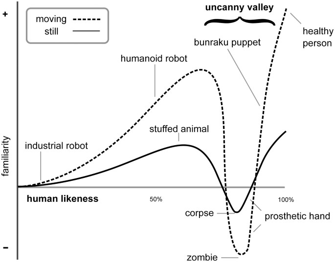
- The Uncanny Valley provides issues for affinity to virtual environments
Interaction
- Consists of locomotion which is the movement of a virtual avatar corresponding to movements in real life
- Matched Zone: Since the VR area is larger than IRL, a matched zone is employed to map the IRL area to a small portion of the VR area
-
Remapping: The mapping of an action IRL to an action in VR (i.e. WASD to move)
- The greater the mismatch between VR and IRL, the more remapping required
- Mismatched obstacles can either be dealt with by drawing a virtual boundary on IRL objects (breaks immersion) or freeze rendering when hitting a virtual object (can cause discomfort when moving IRL but not moving in VR)
-
Redirected walking lets people move IRL and feel like they’re moving in VR
- Subtly change angles and distances (e.g. move 2 m/s IRL and 4 m/s in VR) during saccades/blinks to travel greater distances
- Redirect users (teleportation, distractors) at the end of the matched zone
- Take advantage of change blindness by changing things when user isn’t looking; most users won’t notice
- Can think of a matched zone as a cart that moves through the virtual world using controllers and head rotation
- Starfing: Allowing lateral motion during speed up or slow down in one direction
- Collision detection (between hand and scene) is expensive since you must compute millions of intersections between triangles
- Use a bounding volume to roughly see if objects collide, simpler structures lets you reject intersections easier
- Bounding volumes can be axis-aligned or object oriented
- Spheres and rectangles have easy computations but are worse fits; shells and hulls have better fits but are harder to compute
- Axis-aligned boxes are the most common due to its fast compute and relatively good fit
- To create a tight fit axis-aligned bounding box, engines use an octree data structure
- Generate one large bounding box (root node) and split it into 8 equally sized bounding boxes (children nodes); repeat this process for each node until the box is a tight fit
- Done in preprocessing
- To check for intersection, check root nodes of objects A and B and recurse down the tree until the intersection of two leaf nodes is found
- Techniques for comfort
- No gorilla arms
- Select with flashlight as opposed to a laser pointer
- Don’t force players to continuously press a button; use a state machine (holding vs. not holding)